- 38 Posts
- 182 Comments

 10·15 days ago
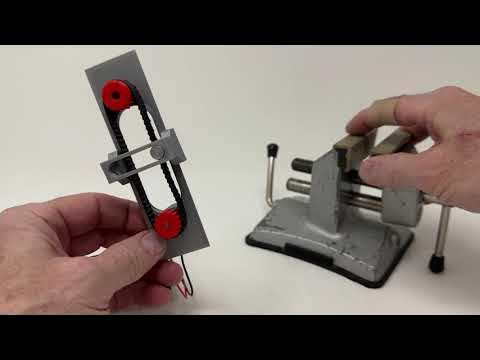
These are basically timing belts for cars. Inside the belt are usually metal or aramid fibers that prevent any elongation of the tooth pitch. A lot of the automotive aftermarket principals of a timing chain versus a timing belt drive apply exactly the same here. The belt lasts longer and operates dry with more accuracy over time.
The positives of a belt drive are maintenance, and that it stays clean so they are most popular with commuters that do not want a dirty pants leg or newbie chain tat. They are only common on heavier bikes like short haul commuters in general and require a “broken frame” that is designed for them in the first place. The lack of transmission gearing means you need to either know exactly what gear ratio you need and deal with only having one speed or you need an internally geared hub. All internally geared hubs have monstrous weight to add. So in practice, you do not find many of these on the market. Even with an e-bike, you still need a geared transmission unless you have throttle control without pedaling.
On the other hand, for a hipster roadie, a fixie with a belt drive is some serious cred. Especially if they can dish it at the local group ride against people on flagship bikes.
No. AFAIK the primary issue is that microcode is not open
 51·18 days ago
I’ve had this happen with AI stuff that runs in a Python venv. It only happens with apps that use multi threading, and usually when something is interrupted in an unintended or unaccounted for way. I usually see it when I start screwing with code stuff, but also from changing the softmax settings during generation or crashing other stuff while hacking around. There may be a bug of some kind, but I think it likely has more to do with killing the root threading process and leaving an abandoned child that doesn’t get handled by the kernel process scheduler in the standard way. If this happens I restart too.
No one has fully open source bios, not even S76 last I checked
Wow:
Oleksiy Protas
P.S. “Don’t feed the trolls”
Don’t you worry. Our friend here tried to reply to this message, he did so twice in fact with slightly different wording, but it was full of political rage and tu quoque so I assume he fell victim to the spam filter thanks to you special counter-baiting operation so to speak.
That aside, I did a very superficial search and it seems that the original author had already had a pull being rejected on the grounds it was coming straight from his Baikal credentials. It’s a real pity that an apparently very able engineer is just playing pretend despite knowing full well why is it so that LF migh not want to be associated with Baikal in any way.
Serge Semin
Hello Linux-kernel community,
I am sure you have already heard the news caused by the recent Greg’ commit 6e90b675cf942e (“MAINTAINERS: Remove some entries due to various compliance requirements.”). As you may have noticed the change concerned some of the Ru-related developers removal from the list of the official kernel maintainers, including me.
The community members rightly noted that the quite short commit log contained very vague terms with no explicit change justification. No matter how hard I tried to get more details about the reason, alas the senior maintainer I was discussing the matter with haven’t given an explanation to what compliance requirements that was. I won’t cite the exact emails text since it was a private messaging, but the key words are “sanctions”, “sorry”, “nothing I can do”, “talk to your (company) lawyer”… I can’t say for all the guys affected by the change, but my work for the community has been purely volunteer for more than a year now (and less than half of it had been payable before that). For that reason I have no any (company) lawyer to talk to, and honestly after the way the patch has been merged in I don’t really want to now. Silently, behind everyone’s back, bypassing the standard patch-review process, with no affected developers/subsystem notified - it’s indeed the worse way to do what has been done. No gratitude, no credits to the developers for all these years of the devoted work for the community. No matter the reason of the situation but haven’t we deserved more than that? Adding to the GREDITS file at least, no?..
I can’t believe the kernel senior maintainers didn’t consider that the patch wouldn’t go unnoticed, and the situation might get out of control with unpredictable results for the community, if not straight away then in the middle or long term perspective. I am sure there have been plenty ways to solve the problem less harmfully, but they decided to take the easiest path. Alas what’s done is done. A bifurcation point slightly initiated a year ago has just been fully implemented. The reason of the situation is obviously in the political ground which in this case surely shatters a basement the community has been built on in the first place. If so then God knows what might be next (who else might be sanctioned…), but the implemented move clearly sends a bad signal to the Linux community new comers, to the already working volunteers and hobbyists like me.
Thus even if it was still possible for me to send patches or perform some reviews, after what has been done my motivation to do that as a volunteer has simply vanished. (I might be doing a commercial upstreaming in future though). But before saying goodbye I’d like to express my gratitude to all the community members I have been lucky to work with during all these years. Specifically:
NTB-folks, Jon, Dave, Allen. NTB was my starting point in the kernel upstream work. Thanks for the initial advices and despite of very-very-very tough reviews with several complete patchset refactorings, I learned a lot back then. That experience helped me afterwards. Thanks a lot for that. BTW since then I’ve got several thank-you letters for the IDT NTB and IDT EEPROM drivers. If not for you it wouldn’t have been possible.
Andy, it’s hard to remember who else would have given me more on my Linux kernel journey as you have. We first met in the I2C subsystem review of my DW I2C driver patches. Afterwards we’ve got to be frequently meeting here and there - GPIO, SPI, TTY, DMA, NET, etc, clean/fixes/features patch(set)s. Quite heat discussions in your first reviews drove me crazy really. But all the time we managed to come up with some consensus somehow. And you never quit the discussions calmly explaining your point over and over. You never refused to provide more detailed justification to your requests/comments even though you didn’t have to. Thanks to that I learned how to be patient to reviewers and reviewees. And of course thank you for the Linux-kernel knowledges and all the tips and tricks you shared.
- Andy, please note due to the situation I am not going to work on my DW DMAC fixes patchset anymore. So if you ever wish to have DW UART stably working with the DW DMA-engine driver, then feel free to pick the series up: Link: https://lore.kernel.org/dmaengine/20240911184710.4207-1-fancer.lancer@gmail.com/
Linus (Walleij), after you merged one of my pretty much heavy patchset in you suggested to me to continue the DW APB GPIO driver maintaining. It was a first time I was asked to maintain a not-my driver. Thank you for the trust. I’ll never forget that.
Mark, thank you very much for entrusting the DW APB SSI driver maintenance to me. I’ve put a lot of efforts into making it more generic and less errors-prune, especially when it comes working under a DMA-engine control or working in the mem-ops mode. I am sure the results have been beneficial to a lot of DW SPI-controller users since then.
Damien, our first and last meeting was at my generic AHCI-platform and DW AHCI SATA driver patches review. You didn’t make it a quick and easy path. But still all the reviews comments were purely on the technical basis, and the patches were eventually merged in. Thank you for your time and experience I’ve got from the reviews.
Paul, Thomas, Arnd, Jiaxun, we met several times in the mailing list during my MIPS P5600 patches and just generic MIPS patches review. It was always a pleasure to discuss the matters with such brilliant experts in the field. Alas I’ve spent too much time working on the patches for another subsystems and failed to submit all the MIPS-related bits. Sorry I didn’t keep my promise, but as you can see the circumstances have suddenly drawn its own deadline.
Bjorn, Mani, we were working quite a lot with you in the framework of the DW PCIe RC drivers. You reviewed my patches. I helped you to review another patches for some time. Despite of some arguing it was always a pleasure to work with you. Mani, special thanks for the cooperative DW eDMA driver maintenance. I think we were doing a great work together.
Paolo, Jakub, David, Andrew, Vladimir, Russell. The network subsystem and particularly the STMMAC driver (no doubt the driver sucks) have turned to be a kind of obstacle on which my current Linux-kernel activity has stopped. I really hope that at least in some way my help with the incoming STMMAC and DW XPCS patches reviews lightened up your maintainance duty. I know Russell might disagree, but I honestly think that all our discussions were useful after all, at least for me. I also think we did a great work working together with Russell on the DW GMAC/QoS ETH PCS patches. Hopefully you’ll find a time to finish it up after all.
Rob, Krzysztof, from your reviews I’ve learned a lot about the most hardwary part of the kernel - DT sources and DT-bindings. All your comments have been laconic and straight to the point. That made reviews quick and easy. Thank you very much for that.
Guenter, special thanks for reviewing and accepting my patches to the hwmon and watchdog subsystems. It was pleasure to be working with you.
Borislav, we disagreed and argued a lot. So my DW uMCTL2 DDRC EDAC patches even got stuck in limbo for quite a long time. Anyway thank you for the time you spent reviewing my patches and trying to explain your point.
- Borislav, it looks like I won’t be able to work on my Synopsys EDAC patchsets anymore. If you or somebody else could pick them up and finish up the work it would be great (you can find it in the lore archive). The patches convert the mainly Zynq(MP)-specific Synopsys EDAC driver to supporting the generic DW uMCTL2 DDRC. It would be very beneficial for each platform based on that controller.
Greg, we met several times in the mailing lists. You reviewed my patches sent for the USB and TTY subsystems, and all the time the process was straight, highly professional, and simpler than in the most of my other case. Thank you very much for that.
Yoshihiro, Keguang, Yanteng, Kory, Cai and everybody I was lucky to meet in the kernel mailing lists, but forgot to mention here. Thank you for the time spent for our cooperative work on making the Linux kernel better. It was a pleasure to meet you here.
I also wish to say huge thanks to the community members trying to defend the kicked off maintainers and for support you expressed in these days. It means a lot.
A little bit statics of my kernel-work at the end:
Signed-off patches: 518 Reviewed and Acked patches: 253 Tested patches: 80
…
Best Regards, -Serge(y)
Kreg moved to Europe, last I heard. So at least the heir apparent is in a region with better potential international diplomacy and neutrality.
That is what I meant by configure. You’re not going to HP to download your printer driver or realtek to get one for your network adaptor. To the end user, the kernel includes the required modules, or it is a matter of simple configurations. The exception being proprietary garbage. However with Nvidia on Fedora, it is a non issue as the Anaconda system builds the Nvidia module from source with every kernel update from outside of the kernel but under the shim, so even secure boot works.
The OP was not asking computer science OS 101. My reply is just intended as a surface level to cause them to question the drivers mentality. I’ve seen many people follow this logic and not get anywhere.
Indeed, gaps are present in my knowledge. I understand what you wrote, in theory, but vaguely based on my reading from a forum on kernel architectures several years ago. I’m most familiar with the user experience of configuring a custom Linux kernel with Gentoo versus needing a WiFi driver that I need WiFi access to source.
Since you are touching on a gap in my knowledge, perhaps a more recent issue and curiosity will help me ground this a little better if you do not mind responding. What is the deal with secure boot and Windows drivers? How are they able to run some random driver from the internet that has DMA?
Software neutrality in the entire public sector should be a law. Leverage of proprietary software and media like professor published book scams are criminal extortion.
That sounds like a hardware issue.
Keep in mind that Linux is a monolithic kernel. It doesn’t technically have drivers at all or go missing. All supporting kernel modules for hardware are always present at the configuration level. The general kernels shipped by distros are configured to work out of the box for most hardware. The only exceptions should be instances where oddball hardware can cause conflicts with the standard way other hardware works in the same space. Then there are cases where hardware is totally undocumented publicly by the chip manufacturers. That is the worst kind as some of those have poor or no support.
By contrast, Windows is a microkernel. It only creates an API layer for the hardware vendor to write a driver that interfaces with Windows. They leave it entirely up to the end user to get stuck in the middle, source and install the driver and deal with any potential issues. In other words they don’t have devs to maintain or do anything meaningful in this space, and they enable undocumented proprietary crap hardware.
 10·22 days ago
No one trusts a mole
Casting is much harder to access now in many urban settings. I wish I could but have no space for it where I live.

The textured Prusa version is still best IMO, (for a textured sheet). I have one of the textured aliex bronze looking plates and the Prusa PEI film/Textured powder coat/Smooth powder coat. I pretty much only use the textured(s) for PETG. I use glue stick or modge podge 10:1 spray for ASA ABS and PC. Texture is irrelevant with adhesive and adhesive cleans off best from the smooth powder coat sheet. That is my universal go-to. I don’t like printing PETG in general unless I design for it specifically.
You need to watch it carefully. PETG has a lot of trouble with moisture. In practice, it has a lot of trouble with seams. When I print PETG, it is not a passive choice, but is instead built into the design. To be fair I pretty much design everything I ever print. I might prototype in PLA and then print in ABS, ASA, or Polycarbonate, but I will not swap to PETG. With PETG I am designing the orientation and features around seam placement from the very beginning to hide them in the middle of the back faces of a parts where they have 4-10mm to start and establish consistency. If I need a better seam in a tighter area, I make a small curved v-groove like the center inner spine of an open book. This feature can be extremely small so long as the mesh resolution can render it and the slicer also picks it up. The groove and curve will place the seam start and end on the inside of the wall just enough to make the ugliness isolated to a smaller area.
This may at first seem unrelated, but I suspect you might find a similar type of issue where starting seams are not attaching properly and causing a cascade of issues.
The actual underlying mechanism to the seam issue is that PETG is extremely sticky when molten. Moisture will sound like little popping sounds in the extruder and these can push out a tiny bit extra of filament. Even with dried filament, PETG will want to create strings on almost every passing surface that so much as looks at the nozzle the wrong way. When PETG goes stringy, it tends to pull more strongly on the melt zone than any other common filament. This tends to pull out more than the typical wisp of a string and instead pulls a slightly larger bit of the melt zone just outside of the tip. This deviation makes seams difficult to ground consistently.
If you try to just go hotter, you’ll ooze more and the problem will be worse. If you try to z-hop higher, you’ll likely find that the string from the last extrude is just as problematic. You might add more retraction, but you’ll still have the previous issue of the last extruded wisp pulling on the melt zone. If you print in vase mode, the problem will disappear, but that is useless advice. PETG can be extremely consistent in performing badly at the seams. This makes it pretty good for print far production in cases like with Prusa. They can dial in every issue on a layer by layer level and achieve prefect and repeatable parts in PETG. I don’t want to print 500 iterations of my design to dial in perfection, so I only use PETG when I can completely hide the seams in the design and create enough margin to avoid any external ugliness. PETG is awesome because it is the only common filament that will conform to the print plate texture with no visible layer lines. This feature is my primary reason for using PETG.
It is just a hunch, but I bet this is a seam issue.
Other than the attempt to obfuscate the TNI and multi-object bodies, what else have they changed in FreeCAD? I haven’t kept up with it, but have seen stuff in passing like Mangojelly’s titles/thumbnails. I like that I learned the proper old skool CAD ways with the TNI, so I kinda lack much motivation to follow the latest nightlys. I’m not trying to gatekeep or anything. It was deeply frustrating to learn the important ins and outs of the topological naming issue and why all proper design revolves around it. If I stayed informed I’d likely be vocal about how people will (likely) fail to learn why things still break in ways they do not understand even though it is entirely their own fault. So I stay a little distant for now and have done so ever since the real thunder drama. Anything new of note?
All of them except the Prusa. They are all proprietary schemes to get you to subscribe to software. There are hacked sub par tool chains to attempt to use them freely, but no one really does it in practice enough that you see them using the thing regularly.
All high resolution displays are proprietary and completely undocumented publicly. Every display is different in how to communicate with it and they change constantly where reverse engineering one will do nothing of value. The next batch of displays manufactured will change in some fundamental way that means the previous reverse engineering efforts must be redone from scratch. Reverse engineering displays and their protocol is a PITA and usually ruins a display or few. You need complex jigs to handle them outside of their final packaged assembly or things break extremely easily. I’ve messed with some smaller simple graphics and LCD displays and reverse engineering, and it is not fun. So you’re unlikely to ever see one of the proprietary resin printers reverse engineered for use with open source software. So full ownership is not an option. It is basically just like bambu but worse. As far as I’m concerned, the Prusa is the only resin printer for sale because I am not for sale/exploitive manipulation, or renting stuff for a one time payment of an equivalent cost of ownership. The Form Labs stuff is probably the prosumer level go-to.
 13·1 month ago
Hazel here, but slowly converting to green team it seems.
Wet filament can do that. Even new filament can be wet some times, especially with rarer colors that sit around in storage for much longer.


Probably the best and safest method is to look into the foam used for camera bags. That is the most common customisable option I know of that is practical. You’ll spend way less time and likely money if you cut foam to fit and pack everything.
Obviously, I’m a fan of 3d printing. Heck I’m beside my printer that is chugging away at a design I made today. However. I think it is a matter of using the right tool at the right time. IMO, big drawer filling organizers are not ideal for printing. I can make wood cardboard or sheet metal boxes much faster and cheaper than printing.
I could see myself designing a quick 2 rail holder with slots for each device to sit within, but that is going to be sloppy and likely wear poorly on the device. Best bet in my opinion is camera bag foam. If it is good enough for a half dozen $1k pro primes in a bag that gets banged around, it will work for some hand helds.