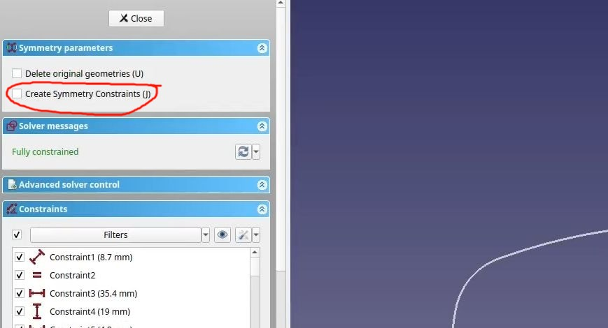
When I do what you did but select “Create Symmetry Constraints” I get a fully constrained result as soon as the Sketcher Symmetry tool is finished. No other action is required.
- 1 Post
- 29 Comments
Joined 1 year ago
Cake day: June 11th, 2023
You are not logged in. If you use a Fediverse account that is able to follow users, you can follow this user.
You didn’t select “Create Symmetry Constraints”. I’m not sure if it will solve the issue completely, but it will probably make some difference.
One thing I see that may come back to bite you later: You can create sketches that make multiple bodies when padded, but I’m not sure why you would want to with the example in this video. If the sketch is two identical bodies mirrored across an X/Y/Z plane use the part design mirror feature and offset the sketch’s attachment not the geometry in the sketch. It works better for that and keeps your sketches simpler, and you get to use symmetry for one side of the two things you are making because the origin will be in the center of one of the objects.
Sketches where the origin of the sketch isn’t the approximate center of a single closed wire are annoying later if you want to reference them in other features or sketches.
Are you making sunglasses? 😎
lol, I just stuck with it I guess 🤣. Seems to work fine
Here’s how it works for me: https://vimeo.com/1019673822
Sorry I forgot to click record cursor. But hopefully that’s clear enough.
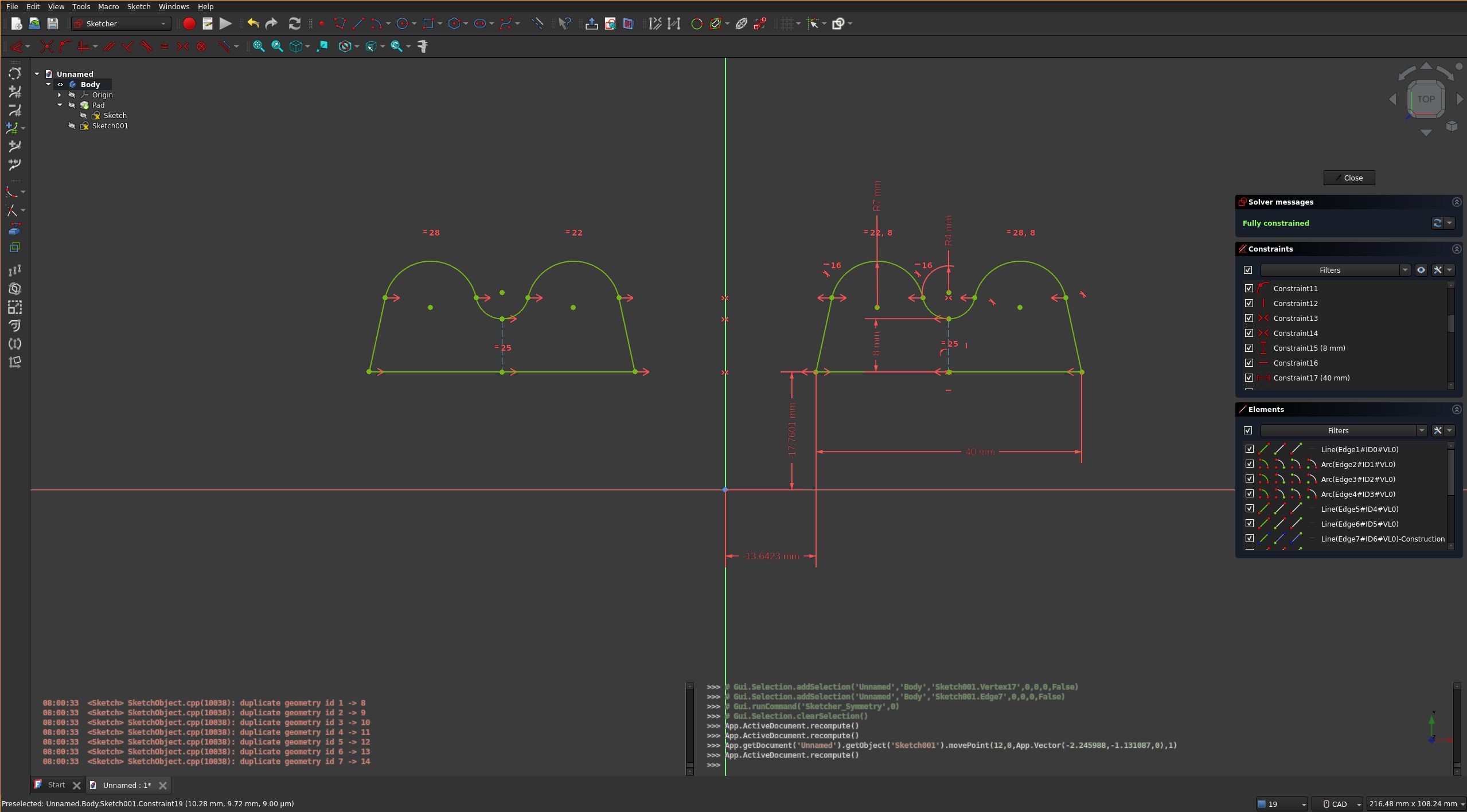
which also makes copies of the constraints which are completely independent from the original constraints on the left-hand side - delete the stupid new right-hand side constraints and slowly, painfully constrain the right-hand side copies to the original left-hand side elements
I feel like this is not how it works for me. It does copy the constraints and automatically create symmetry between any points across the selected center line, but if you’re making a mirror why is that not what you want?
Also I’m unsure about the behavior in older versions of freecad, the behavior of this feature is new in 1.0
You want Sketcher Symmetry but it’s not quite what other CAD packages have. Select what you want to mirror, which is probably the entire sketch using the drag selection box, select the
Sketcher Symmetrytool, then pressJto add constraints.It’s not perfect, I suspect because it can’t read your mind as well as the big CAD packages about where you want coincident constraints for joining lines, but it’s mostly OK.
EDIT: I can’t tell if you are describing the Sketcher Symmetry tool in your 4th paragraph or not. You will sometimes get over constraints where the end points intersect but you can delete them with one click and make those points coincident instead. I suppose this could be time consuming if you have a really really complicated sketch with multiple intersecting points, but that probably wouldn’t pad anyway.

 1·2 months ago
the qobuz webapp is hi-res too, I just use it in Firefox and my dac reports the same bit/sample rate that qobuz does. AFAIK there’s no compression there though I haven’t extensively verified that, only that the end result is 24bit/192kHz if that’s what qobuz says is playing.
EDIT: Also, qobuz is nice because there’s very few things you can click on in the web interface which cause the music to stop playing. I really appreciate that feature… looking at you bandcamp…
Yeah, it changes without skipping a beat for me in pipewire, even in things like zoom/teams.
I use a little oneliner with tofi (rofi/wofi would also work) to select the current output and avoid pavucontrol. It’s mapped to a sway binding but would probably work in any wm/de:
pactl set-default-sink $(pactl list short sinks |awk '{print $2}' |tofi $tofi_args)I’m using pipewire so the functionality of pactl is actually provided through pipewire-pulse I think
 5·5 months ago
What makes those methods better?
Disclaimer, I’m at a sortof “advanced hobbyist” level of cad. My understanding of the topological naming problem in general is that it exists in all cad because it is a sortof byproduct of how computers keep track of data about 3 dimensional objects. If you make a cube, all the sides need to have an identifier associated with them. If you put a hole in that cube, you now have more identifiers and have to decide what ordering makes sense. It sounds easy to work around with a cube but when models get really complex it’s not so easy, especially when you change something way back at the beginning which creates more or less faces in the middle of the list somewhere.
Freecad isn’t making the topological naming problem “go away”. They are creating (or rather merging, it’s been around a long time) an algorithm that makes a better guess at what the order should be, rather than sticking new faces in the list and reordering without any consideration of what happened after that face was created. This is, as far as I understand, also how other CAD packages do it, and you can still back yourself into a topological naming problem if you try hard enough (or don’t try at all I guess) in both freecad with the new changes applied, and in other CAD packages.
So “best practice” is to be smart about the attachment of your geometry thinking about how things might change in the future, rather than clicking the closest face whenever you need a sketch plane. In reality modern proprietary cad is so good at guessing and maintaining consistency that it doesn’t matter unless your model is horrendously complex and whoever made it didn’t pay any attention to laying out the base sketches in an organized way.
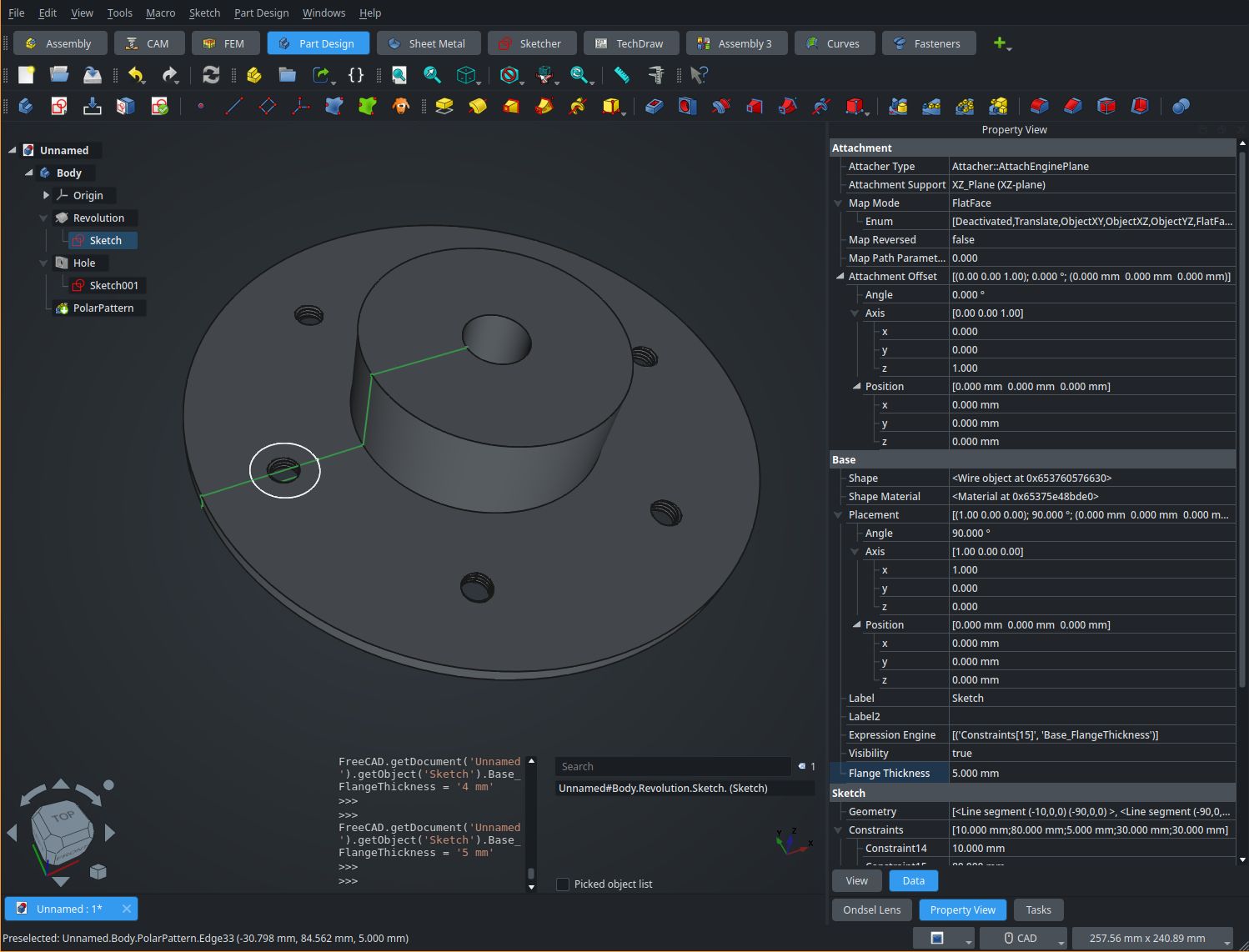
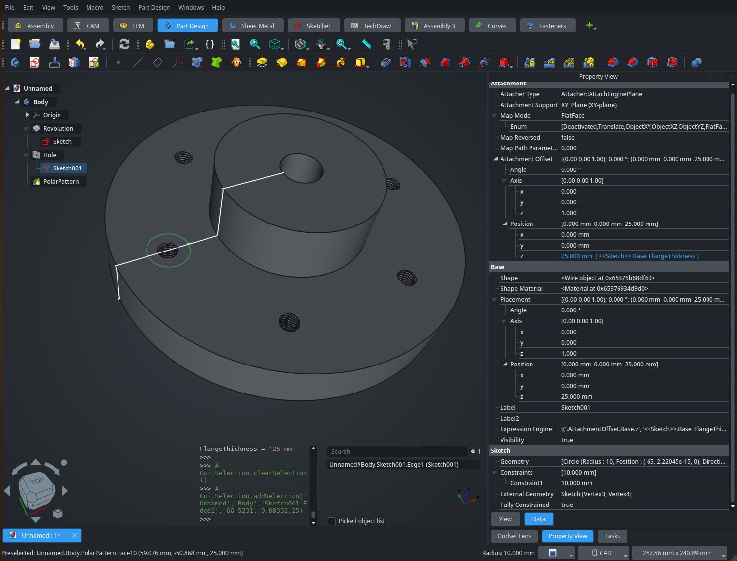
For example if you make a flange but you’re not quite sure about the thickness, base the sketch for say, the holes, on the parallel origin and offset it by the height of the pad or the length of the sketched geometry. Or use a spreadsheet or variableset for the value of both the thing that you define the thickness with, and the offset from the origin plane. That way if the value changes, nothing will break.
I made a test model but it isn’t something that shows up well in a single screenshot unfortunately. See the “Flange Thickness” and z offset parameters in the property view. I used that for the flange dimensions, and the hole sketch offset.
Interesting, it is working for me in wayland and the drop down menus are fine but I’m using sway which is a totally different wayland implementation than what KDE is doing. I’m glad you found a workaround.
Unfortunately I don’t know what is causing the exact issue you are having, however here are a few things I found when doing this myself that are “gotchas” (not immediately obvious).
-
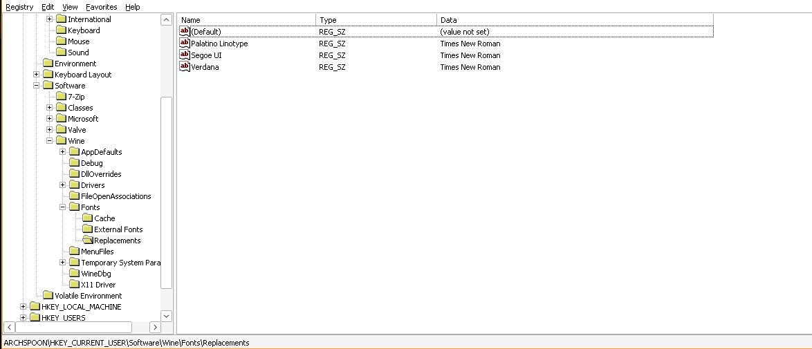
This is the reason your fonts are all Times New Roman. Go to that key using protontricks regedit and delete all the font replacements.
-
Anything you put in
$HOME/.steam/root/steamapps/common/assettocorsastays there, even if you uninstall the game. If you want to “start over” you have to uninstall the game and then delete the whole assettocorsa directory there, and the wine prefix in$HOME/.steam/root/steamapps/compatdata/244210 -
AC and content manager work without .net changes in the latest GE but you do need
corefontswhich you can install with protontricks. If you want to be extra sure you have the right .net you can install dotnet472 but I don’t believe this is necessary anymore as it will be installed automatically or is already installed. You may get a wine .net error the first time you launch the game but it’s only the first time. -
If you choose to use CSP you have to unzip the archive you get from either Patreon or acstuff.ru and manually copy the
dwrite.dllfile into$HOME/.steam/root/steamapps/common/assettocorsaon EVERY upgrade. The zip installer built into CM doesn’t do this correctly on Linux. It will cause rain not to work if you choose to use the Patreon version if you don’t do this manual step.
I think you should start over and make sure the assettocorsa directory is clean before re-installing the game. It could be missing fonts, but it’s hard to say. You can back it up somewhere if you have data in there you need.
-
What version of kde? I haven’t tried it, or read about it beyond the changelog, however the latest beta release says that it supports RDP to connect to plasma desktops which is quite an interesting development if it works the way it sounds like it does:
Remote Desktop system integration to allow RDP clients to connect to Plasma desktops, plus a new page in System Settings for configuring this
For the “from anywhere” component you could use a vpn, but if you’re looking for a simple solution with zero configuration than nomachine or rustdesk seem more appropriate. Just thought the RDP support was worth sharing.
So, I’m not sure if the process has changed in the last decade or so but in a long-ago computer forensics class step 0, before all else, was to never operate data recovery on the original disk. Create a block level image of the entire device, then work on that.
My go to steps for recovery have been the following in the years since:
- create an image of the entire disk (not a partition) using ddrescue
ddrescue -d /dev/sdX <path_to_image>.img - Run test disk on it selecting the partitions as necessary
testdisk <path_to_image>.img
If the disk has a complicated partition layout, or more effort is required to find the correct partition you can also mount parts of the disk.
-
create an image of the entire disk (not a partition) using ddrescue
ddrescue -d /dev/sdX <path_to_image>.img -
Mount the image as a loopback device with the appropriate offset
losetup --offset <some_offset_like_8192> --show -v -r -f -P <path_to_image>.imgthis will mount individual partitions:loop58 7:58 0 465.8G 1 loop ├─loop58p1 259:7 0 1.5G 1 part ├─loop58p2 259:8 0 450.6G 1 part └─loop58p3 259:9 0 13.7G 1 part -
Then operate testdisk on whatever partition you want.
All that said there are a lot of variables here and things don’t always work perfectly. I hope you do find a way to recover them.
- create an image of the entire disk (not a partition) using ddrescue
Sway for a little over a year now (on an AMD gpu). I switched for mixed refresh rate support and VRR. VRR requires a workaround in sway but works better in others, like hyprland, however I like sway’s tiling better so I stuck with it. Also the absence of tearing in anything, ever, is worth it to me. I have two vertical displays and it was really hit or miss on X11. Sometimes GPU acceleration would just decide not to work in browsers and I’d have to restart them because smooth scrolling would turn into a stop-motion film. That’s never happened since switching to sway.
EDIT: I used i3 before
I use sway and run zoom in my browser (because zoom is shady and I don’t trust them). Screen sharing works fine in the browser. The application never worked very well to being with anyway for me, even on X11.
I also use https://git.dec05eba.com/gpu-screen-recorder/about/ for individual output screen recording such as gaming which works amazingly well. You can not select a section of a single output though, only the whole output. That’s a deal breaker for some, and a non-issue for others, just depends on what you need.
Yeah that’s fair, I do think that a big UI/UX redesign that makes it magically user friendly in a single release cycle would be next to impossible with the funding the project has though, and unfortunately a long drawn out redesign (what’s currently happening with, say, RT’s UI improvements) would likely have a lot of the problems that got us to this point as well. UI/UX benefits from a closely integrated team working towards a singular goal in my (limited) experience.
Now that I’m thinking about it a bit more, the project moves very slow and is for some reason extremely cautious about contributed core code so when things do need to be improved they become workbenches or addons and splinter the workflow even more.
This PR for example was a massive hurdle for some transparent overlays and went quite quickly in comparison to other features https://github.com/FreeCAD/FreeCAD/pull/7888
FreeCAD is the way it is mostly because it’s not optimized by multi-billion dollar companies with teams of developers and UI/UX engineers. It’s very much the do-all-the-steps-your-self CAD package.
That said, there are loads of bad or outdated video tutorials out there, and generally people tend to find one way to do a thing and then market their video as THE way to do it. Treat FreeCAD like Linux, there are lots of “correct” ways to use it, and also don’t expect it to be something it’s not.
If you feel comfortable with it, it would be cool for you to make a short video of where you are stuck, or where you feel you are doing unnecessary steps, and maybe we can help you reach our goal in a simpler way?
“An attacker would need to be able to coerce a system into booting from HTTP if it’s not already doing so, and either be in a position to run the HTTP server in question or MITM traffic to it,” - Matthew Garrett
Summary left out a quite important bit.
Ah, I see. I imagined your use of that sketch differently. Looks good!