I would like one industrial replicator, please.
- 4 Posts
- 49 Comments
Joined 9 months ago
Cake day: February 15th, 2024
You are not logged in. If you use a Fediverse account that is able to follow users, you can follow this user.
I have no idea if this is a clever bypass around expensive commercial offerings, a clever waste of time that barely improves over doing it by hand, or somewhere in between, but it sure looks like a nice design and print.

 7·2 months ago
I suppose if a given machine can work in LAN or sneakernet mode, then it’s not THAT bad, but I was referring more to their heavy reliance on Cloud, closed source (possibly in violation of other projects’ licensing), and proprietary parts. If any 3D printer maker is going to start hiding features behind a paywall someday, it’s them.
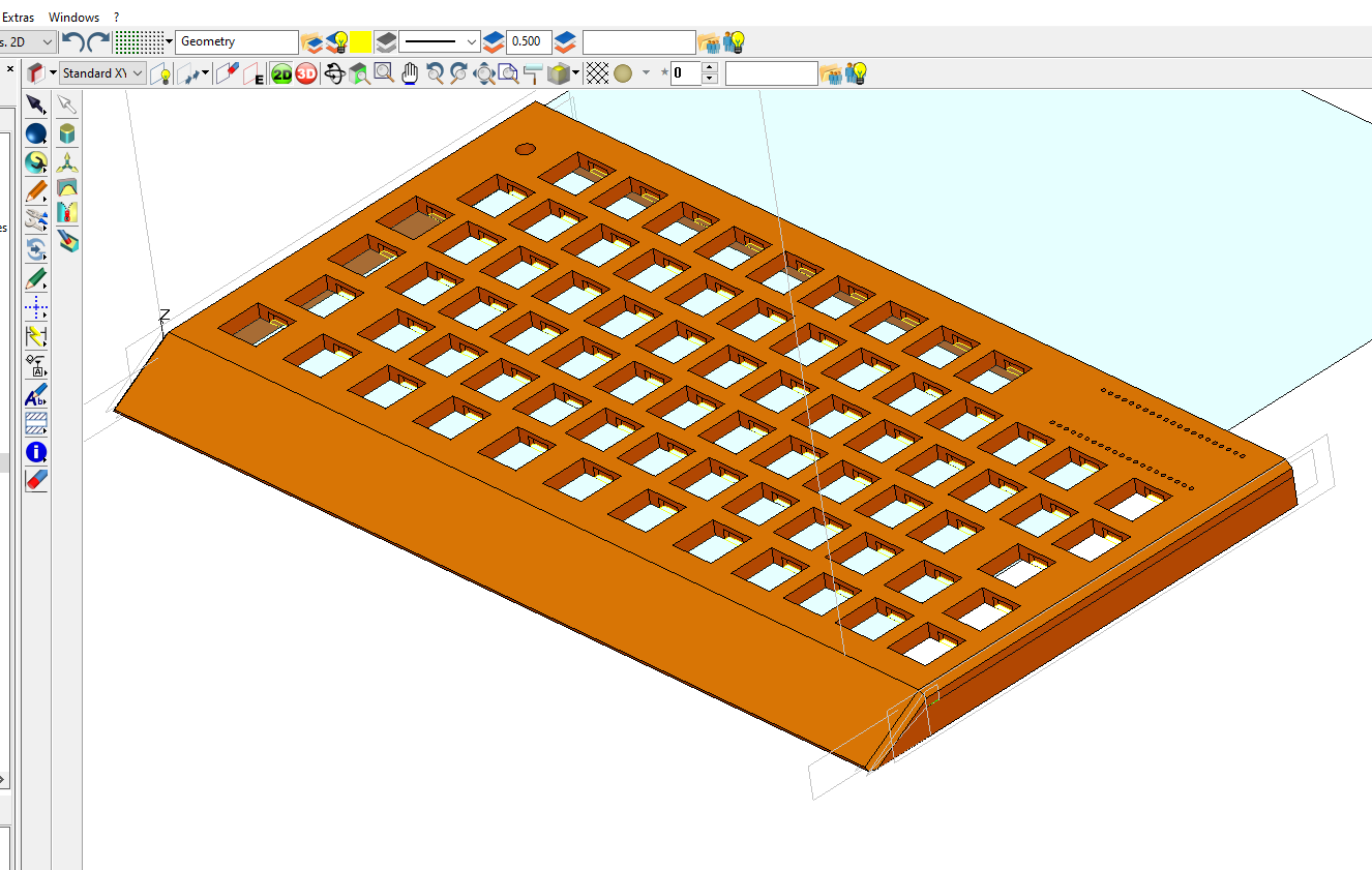
I was thinking the Neptune 4 plus looked pretty good. If I can get my print capacity to 300mm in X and Y, options for my other hobbies (keyboard building in particular) open up. Then, I’ve never really tried TPU, so direct drive also seems nice.
A big Core XY for under $600 seems nice. Have to consider it.
The only other disadvantage I can think of is smaller dimensions in X and Y. At a minimum, I’d like to be able to keep printing 200+ mm squares. The inherent speed and stability seem nice, though.
In that case, I would recommend starting with FreeCAD (get a 1.0 release candidate from the weekly builds github) and make sure to watch a couple of intro tutorials. There are tons of CAD packages with pluses and minuses (and that’s exaggerated in their free tiers), but if you can start with FreeCAD and have it as your baseline, you can avoid a lot of cost and annoying business practices, though as I mentioned elsewhere, Plasticity is not a bad choice if you go in knowing its limitations.
I’ve done the trial, and included it in my stickied writeup at !cad@lemmy.world
It’s not parametric, and for amateur single-part designers the biggest thing there is just that it sucks to realize you screwed up a a height or distance somewhere, and now you have to go back and Boolean on some shape or adjust a bunch of screwholes manually. Constraining drawings and using variables is all very nice if you start making more sophisticated parts or really need to churn them out quickly, but the History is the beautiful part for this use case.
Other than that, I actually liked it quite a bit. The workflow is pretty intuitive, it works smoothly (on Win10 at least), and it has literally the nicest and most ambitious fillet/chamfer heuristics of anything I tried. It will try its best to fillet things right into oblivion.
My only other real concern is that it’s a one-man shop, but if it works mostly bug-free for you, that is not necessarily a huge deal, especially at the price point. I think it’s probably a pretty good value, but I already have a non-parametric app I can use well enough, so I went with Alibre Design on a payment plan, so it feels like a slightly expensive subscription, but then I own the license. I’m still hoping FreeCAD 1.0 will be good enough to make me regret the decision to go with Alibre, but we’ll see.
This discusses the pontoons and the partyboat or “pleasure boat” as it’s referred to in the article. They can be very stable, but they need to be pretty wide and as they saw in the video, you still want the boat to ride pretty low in relation to the size of pontoons you use.
A daggerboard is a type of centerboard that can be pulled up through a slot in the hull. Centerboards are mostly used in sailboats, but the reason they’re needed is that in terms of forces acting a boat, sailing makes it top-heavy as removed. This benchy is naturally top-heavy, so having a fin sticking down in to water helps, and having a weight on the end of it helps even more.
Ultimately, I imagine they ran across most of these concepts in preparing the video, but it wasn’t as fun for their intended audience as a silly low-stakes 3D Printing YOLO meme, and TBF the 3D printing seems to have come off very well.
So I think the little bit they added is still there, but it just wasn’t nearly enough. TBF, there’s nothing inherently “wrong” with making a boat wider rather than deeper (e.g. the aforementioned partyboats), but as they saw it doesn’t scale quite how you’d think, and much of the benefit they got from the pontoons that did work would have been there even if they’d left it flat.
Also, I guess the apparent half-assery is part of the appeal? I am not familiar with this Emily. I kind of assumed it was going to be an Emily Calandrelli video, but then I’m a dad who’s watched a LOT of kids’ Netflix.
Of course the Southerner headin’ out to the lake thinks of pontoons like a partyboat instead of a daggerboard or other weighted keel. LOL. This tracks with my life experience.
I mean yes, in a certain sense mbin is exactly how open source is supposed to work when things go sideways: fork the code, change the name, leverage the original work, leave Ernest in peace, whatever he’s dealing with.

Realthunder has been working with the main team to get his toponaming fix into mainline FreeCAD, and they’ve already adopted several of his UI improvements and settled on an assembly workbench. Version 1.0 should finally be released by the end of the year, and the weekly builds are promising. I don’t know if it’s quite there for me yet, but I’m hoping it will be by the time my paid-for Alibre is feeling long in the tooth, and any CAD DIY enthusiast would be wise to keep half an eye on FreeCAD.
I did a quasi-deep dive into licensing terms of the various suites. OnShape’s free tier is particularly clumsy, and on a facial reading bars you from using your own designs commercially, but allows you (and literally every other user) free rein on other people’s designs. It’s quite odd and will probably need litigation to sort out. Then they have nothing between the free tier and the $1800/year tier.
Fusion gives you, IIRC, a grace zone of a thousand bucks of revenue a year before it counts as commercial and you have to get the $600/year paid plan, which seems suspiciously close to how much profit a no-overhead side hustle might pull from $1000 of sales. Solidworks hobbyist gives you $2k of profit grace per year, and when combined with a Titans of CNC discount, makes it a pretty good option for the “let me sell a couple of things on Etsy crowd,” but it’s a much bigger price jump than Fusion if you need to get a commercial license (basically about $2000 a year, I think… sensing a pattern here).
Solid Edge keeps it simple and just says that the free version is for non-commercial use only, though as a locally installed app I’m surprised it’s not more popular.
I was continuing to struggle with FreeCAD, though it’s getting better with every weekly release, and they have a little bit of outside money coming into the project now. Still, I “treated” myself to a $700 permanent Alibre license. I like the workflow and the focus on the workbenches I actually use, and after ten payments I’ll be able to use this particular version however I like for as long as it runs. Not perfect, being closed source and Windows, but they’re a responsive small company in a crowded space, so I don’t think they’re going to removed over the paying customers too badly.
Yes, I know, possibly one absurd enough to invite the 3D printing equivalent of a dad joke. :-)
Oh well, like I tell my kid obsessed with potty humor, not every joke lands.
deleted by creator
Not food safe.
Be careful… IIRC, DeWalt batteries actually rely on circuitry in the tools, and it’s possible for an old tool to over-discharge them and reduce their capacity pretty drastically. Specifically, it seems the “low voltage cutoff” lives in the tool for DeWalt (and Makita and Milwaukee I think), while Ridgid, Ryobi, and B&D have it in the battery. The two former are for backwards compatibility, and I think the latter because god knows what stupid garbage tools they’ll throw at the line next (though my B&D sander is… fine).
The pinout on the orange B&D is exactly the same as PC 20v, and there’s only like two little nubbins of plastic on the battery case, and two tabs on the PC tools that make them physically incompatible. I use them interchangeably after some dremel engineering (that gets nowhere near the electricals). Same as those now-retired Bostitch 18v, and I understand non-US “fat max” batteries and a certain limited line of 20v craftsman stuff from a decade ago is also the “same.”
The newer Craftsman that S-B&D makes looks to have been designed along similar lines, but they flipped + and - and added enough plastic-work that I think it’d be non-trivial to hack them up. I haven’t investigated to see whether, electrically speaking, they are more B&D or more DeWalt.
Voyager has been working well for me.